Northeastern Electric Racing
Chassis Lead
I led the design, simulation and manufacturing of the Northeastern Electric Racing team's chassis for the 2024 competition year according to FSAE rules.
Summary
What was this project?
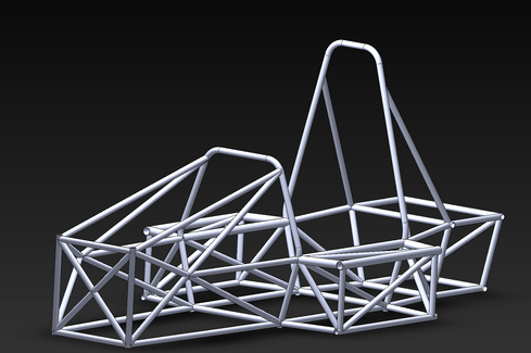
Designed, simulated and manufactured a rules-compliant, FSAE style, space frame chassis for the 2024 Northeastern Electric Racing car. The chassis was strong, light and stiff. It was design with the integration of other components and manufacturability in mind.
How was it executed?
Using the SolidWorks 3D sketch tool, the outline of the chassis was created with a predetermined set of nodes. Weldment features were then used to select tube sizes and prepare the structure for simulation. Simulation results confirmed that the chassis could withstand the loads it would experience in a crash.
Finally, a jigging system was designed to allow for accurate construction of the chassis.
What was the results?
This chassis was 28% lighter than the previous version as a result better material choices. It had the best torsional rigidity of any NER chassis to date, at 2000 N·m per degree.
Design Constraints
01.
FSAE Rules
02.
Driver Anthropometry
03.
Budget
04.
Impact Ratings
05.
Manufacturing Capabilities
Design Goals
01
Minimize Mass
The mass of an FSAE car is one of, if not the biggest, factors that contribute to performance. Chassis mass accounted for roughly 20% of the previous car's mass, and in this design cycle, a significant overall mass reduction was targeted, as well as a decrease in the chassis' contribution to the total mass of the car. Hence, minimizing chassis mass was crucial.
02
Maximize Chassis Torsional Rigidity
As the chassis is generally considered to be a rigid body in suspension design, it is vital that the chassis is as stiff as possible. A flexible chassis can make the car undrivable!
03
Ease of Component Integration
The chassis integrates all car components to form a cohesive package. Each component of car has different needs from the chassis, and often these needs are opposed to an optimal chassis design. The design of this chassis aims to fulfill these needs (mounting points, access, clearance, etc.) while retaining good performance.
Manufacturability
04
The previous chassis was not manufactured accurately and had multiple difficult-to-weld joints. A major design goal for this chassis was to reduce the number of complex welds and to design with accurate manufacturing in mind.
Material Selection
Material selection for this frame chassis was limited to two main candidates: 4130 chromoly steel and 1010 carbon steel. These two materials were chosen because the welding team had experience with them, and in the interest of manufacturability, a decision was made to limit the material search to these two options.
Property | Mass Density (g/cm^3) | Ultimate Tensile Strength (MPa) | Yield Strength (MPa) | Young's Modulus (GPa) | Elongation at Break | Brinell Hardness | Price Per Kg |
|---|---|---|---|---|---|---|---|
4130 Chromoly Steel | 7.85 | ~670 | ~440 | 190 | ~26% | 200 | ~ $1.4 |
1010 Carbon Steel | 7.87 | ~350 | ~190 | 190 | ~31% | 100 | ~ $1.2 |
Chassis Design
Compliance
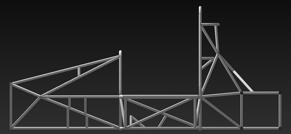
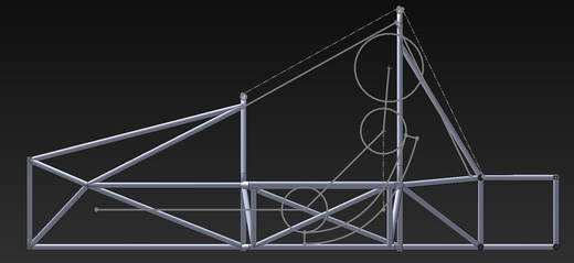
The images displayed above demonstrate the various constraints around which the chassis was designed. A significant amount of time and effort was dedicated to optimizing the roll hoops to ensure a low center of gravity while simultaneously providing a sufficiently large rollover envelope to ensure the safety of all drivers. Additionally, the chassis incorporates raised side-impact structures and sturdy harness bracing nodes and bars to further enhance safety measures. The chassis passed scrutineering on the first attempt and was not flagged in document reviews for any further rule investigations.
Integration
Given the critical role of the chassis as the foundation of the vehicle, we invested significant time, effort, and consideration into ensuring that all major sub-systems were equipped with robust mounting locations. In some instances, we opted to prioritize structural integrity over weight reduction, recognizing the importance of secure mounting points. Our team determined that incorporating additional lighter members in select areas was a more effective approach than adding mass in critical members. Notably, we meticulously evaluated and reinforced the load paths from the front and rear suspension mounting points to optimize performance.
Performance
By optimizing the tubing thicknesses throughout the chassis, a significant weight reduction of 28% was achieved compared to the previous version. This led to the best torsional rigidity of any Northeastern Electric Racing chassis to date, measuring over 2000 N·m per degree. Safety was the top priority for our team's first taken to a national competition, and these enhancements did not compromise it. Furthermore, the chassis exhibited the best accuracy and reduced mounting complexity for major components due to efficient packaging.


Analysis
Finite Element Analysis - Torsional Simulation of Chassis
01
Meshing
In consideration of software limitations, beam elements were selected as the analytical method for the chassis study. A comprehensive investigation was carried out to ascertain the convergence size of the beam elements, which was determined to be 0.325 inches per element. Furthermore, localized mesh refinement was executed around the roll hoops to enhance the accuracy of the analysis.
02
Boundary Conditions
In order to accurately replicate real-life load paths, the rear chassis inboard suspension mounts were chosen as constraint points. The 3-2-1 constraining method was then applied to restrict all degrees of freedom in the rear of the chassis without over-constraining the simulation. To calculate the torsional rigidity of the chassis, loads were applied vertically in opposite directions at the shock mounts in the initial version of the simulation, creating a moment around the car's longitudinal axis.
03
Results
The objective of this study is to gain an understanding of the displacement and deflection that occurs in chassis. It is noteworthy that the chassis is only deflecting in the xy-plane (which is the front plane in this coordinate system) due to the axis of rotation being the normal vector of this plane. We can see from the plot that the maximum deflection was about 12 mm with a point load of 1000 N applied on each side (although this is not in the area of interest). Sensors were placed in a series of longitudinally collinear points and recorded for during analysis.
04
Further Analysis
Further analysis was needed to translate the raw data into actionable insights. The team was targeting a torsional rigidity of 2000 N·m per degree (a target derived from research and suspension requirements). I translated the displacements measured in the simulation into a torsional rigidity for each sensor, and then we could map these onto the profile to see which sections of the chassis were stiff and which needed further work. From here, the cycle continued as we iterated over designs.
Note that this is an example of one simulation I conducted for this project! I performed this simulation using multiple methods to triangulate the data and help us determine an number for our final. Frontal, rollover, side, and rear impact simulations were run, and some other performance characteristics, such as the loads on the chassis under maximum braking, were also assessed.
Manufacturing
The manufacturing process of Northeastern Electric Racing's car for the 2024 competition year
VR3
Worked with the vendor, VR3, to precisely CNC mill the notches in our chassis tubes
Jigs and Fixtures
Designed and manufactured (waterjet and laser cut) a 3 part jigging system to manufacture the most precise chassis the team has ever made
Welding
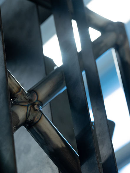
Prepared tubes, oversaw assembly and managed the welding team to produce an on time chassis. The chassis was welded using TIG and ER80S filler


Stage 0
The first step in the manufacturing process was to produce the drawings, BOM, and CAD files for a quote from the vendor. After making some minor design refinements (changing the trim philosophy) to suit the vendor's tube notching process, we submitted a purchase order.
We were manufacturing the tubes while I designed and built our jigging, the philosophy explained below. The fixtures were predominantly made from 10-gauge hot-rolled sheet steel using a waterjet. We also added some 1/4" MDF to the base of the jigging to provide extra support for the parts that slot into it.


Stage 1
Our chassis manufacturing began at the most obvious point: all the planar faces on the chassis. I constructed pegboard plates that had transition fits for the 1/4" x 2" precision dowel pins we had in stock. These pegs constrained each tube in four degrees of freedom, and then we added pipe clamps and C-clamps to secure each tube in place. Access holes were added so the welders could reach narrow gaps from the opposite side. The planes manufactured in stage one can be seen in the middle image above. We also created a 'base' pegboard that served to locate the entire chassis. All the other fixtures slotted into this pegboard, which constrained the lower chassis tubes along the length of the car. This pegboard was bolted down to the flat (and stiff) weld table to ensure alignment.


Stage 2
In the second stage of the process, the chassis was brought to life through the implementation of a system of primary (blue) and secondary (grey) jigs. These fixtures were utilized to ensure precise alignment between the tubes while also holding the previously constructed faces in place. This approach resulted in a stable and highly accurate assembly. Notably, the chassis was constructed in three steps at this stage, with the middle three images showcasing the backward growth of the structure. This method allowed welders to access challenging joints with greater ease and efficiency.


Stage 3
The final major manufacturing was to install the mounting and support tubes. This was done, as it depended on how accurately both the chassis and suspension control arms were manufactured. The fixtures were designed with adjustability in mind, but due to the high accuracy of both the chassis and control arm manufacturing, it was not needed. At the end of Stage 3, the fixtures were removed destructively, leaving behind a complete chassis.
Further Steps
After all the weld tabs were added, the chassis was cleaned and prepared for painting. Multiple coats of hard spray paint were added for aesthetics and rust protection.
Results
The chassis had the best linear accuracy of any chassis Northeastern Electric Racing had produced. All major linear dimensions were within 0.2% of the design dimensions and critical nodes were within 0.3% of their targets.
