Multipurpose Droplet Impact Chamber
A chamber engineered to study droplet impacts at positive and negative pressures
Overview
What
A versatile research chamber designed for droplet impact studies, capable of operating under positive pressure and medium vacuum conditions. Used in early disease detection and other biomedical research, it provides:
Optical clarity throughout for precise high-speed imaging.
Pressure control to simulate various environmental conditions
Customizable setup to support diverse experimental needs.
How
Starting the design process with background and market research, the project transitioned into
into conceptual design and initial prototyping, refining feasibility and functionality. Using SolidWorks, MATLAB, and SolidWorks Simulation, the design matured into a safe and manufacturable product, with structural integrity and performance front of mind.
While parts were being fabricated, the electrical system was developed using Fritzing. A basic C++ control system was then written to manage the chamber’s electronic components. To ensure reliability, pre-assembly testing was conducted on individual subsystems, validating performance before final integration.
Result
The system was delivered with functional electronics, a droplet ejection system, transparent chamber and stand that allowed for safe, efficient and accurate operation of the system. Within the designated time frame and under the budget.
Drop Height - 16 inches, exceeding the stretch goal of 15 inches
Transparent system - allows for adequate lighting
Safe - multiple safety systems like pressure relief valves, E-stops and auto-pump shutoffs
Quick Links
Key Theory
Vacuum behavior is governed by three fundamental laws:
-
Ideal Gas Law – In ideal gases, density changes are directly related to pressure and inversely to temperature.
-
Boyle’s Law – At constant temperature, gas pressure is inversely proportional to its volume.
-
Dalton’s Law – In a gas mixture, total pressure equals the sum of individual gas pressures.
Vacuum ranges are classified by molecular density. As density drops, conventional pumps become ineffective, and classical gas laws begin to fail. To address this, the Kinetic Theory of Gases models gas as a collection of individual, randomly moving particles. Gas pressure results from particle collisions, which decrease as molecular density falls.


Background Research


Current Solutions
Large Drop Height
Continuous Transparency
The Northeastern MIE Liquid Surface Interaction Lab faced a unique challenge as no existing market solutions met their requirements for a large drop height, low budget, and high optical transparency.

Market Demand
Market research shows that droplet research has surged since 2015, driven by its critical role in semiconductor manufacturing. This growth signals strong potential market demand for research apparatus that aid researchers in this field.
High Potential Market Demand
Design Goals
01
Positive and Vacuum Pressure Operation
The system must operate across a wide pressure range, from 30 psi absolute down to 15 Torr (0.29 psi), ensuring functionality under both pressurized and vacuum conditions.
02
Large Drop Height
The chamber design targeted a 12-inch drop height, with a stretch goal of exceeding 15 inches to expand experimental capabilities.
03
Optical Transparency
The chamber required optical transparency to meet the lighting needs of the high-speed camera. Since a sufficient lighting system was already in place, no additional investment in lighting was necessary.
Design
System Overview

Full System
The integrated system consists of a support stand (blue), a droplet ejection system (pink), a transparent chamber and electronics to control ejection and record data.


Pressure Chamber
The chamber is the heart of the system. Flat viewports on the top and side allow for excellent image capture of the research taking place. These faces are sealed with 8 bolts torqued to 150 ft-lb, compressing an O-ring with a hardness of 70A. Sealed bulkhead fittings on the base transmit electronics, relief valves and pump fittings into the chamber.


Droplet Ejection System
The droplet ejection system uses a linear actuator to eject the experimental liquid from a gas-tight syringe. The system has heating capabilities to control the viscosity of the ejected substance. Adjustable rails allow researchers to configure the system to their needs. At the base, an impact surface is coated to be hydrophobic and is replaceable for different experimental configurations.


Stand
The stand supports the chamber and provides stability during operation. It serves as a mounting point for experimental hardware (high-speed cameras and lighting) and houses the electronics enclosure. The chamber can be quickly removed for cleaning, while being locked in place for experiments


Electronics
The electronic system runs off an Arduino Uno R4 to collect data and control the system. Relays control the heating of the system and an H-bridge runs the linear actuator forward and rearward to eject droplets or retract the syringe for loading. Three thermocouples collect data on the temperature at the syringe and are used prevent thermal runaway.
Bill of Materials
The system had a total of 36 COTS parts and 15 custom manufactured components with extra parts being purchased for R&D and testing. The total project cost $2581.5

Material Selection
Ashby Selection Methodology

A key challenge in the design process was identifying a material that balanced optical transparency with structural strength to withstand pressure variations. This required a methodical approach to ensure the best trade-offs between clarity, durability, and manufacturability.
To achieve this, the Ashby Selection Methodology was employed, providing a systematic framework to compare materials based on mechanical properties, transparency, and pressure resistance.
The first step in this process is to filter a database on a set of primary design requirements. In order to keep the search wide, this started with a transparency filter.


Manufacturing
To optimize manufacturability and assembly, multiple design revisions were made, focusing on both accuracy and ease of fabrication for key machined components. Examples of this include revisions to the flange to reduce the tolerance stack between this component and the cylinder.
A primary concern was sealing integrity, making ease of assembly crucial. To achieve this, close collaboration with the machine shop ensured that only critical dimensions were tightly specified, reducing unnecessary constraints. These included:
-
Flatness of sealing surfaces to ensure proper vacuum sealing.
-
Critical O-ring dimensions for effective pressure retention.
-
Surface profile tolerances to maintain precise fits and prevent leaks.
Component Specifiying
To ensure the best components were chosen, a rank-choice decision-making process was implemented. This structured approach allowed for objective, data-driven selection by evaluating components based on key performance criteria. The process followed these steps:
-
Rank Objectives by Importance – Identifying and prioritized design requirements relative to each other.
-
Assign Weights to Objectives – Weighting each criterion based on its impact on performance and feasibility.
-
Research & Collect COTS Parts – Identifying commercially available components that met project specifications.
-
Score & Calculate Utility – Evaluated each component against the weighted criteria and calculated a total utility score to determine the best option.


Analysis


Hand Calculations
Hand calculations played a critical role in two key stages of the design process:
Design Space Exploration & Optimization
Generated design space graphs to visualize optimization opportunities. These guided major decisions, including overall chamber dimensions and pump specifications based on performance trade-offs.
Structural Safety & Validation
Calculated safety factors, yield stresses, and joint integrity to ensure chamber reliability. Which served as initial validation checks before running Finite Element Analysis (FEA) to verify results.


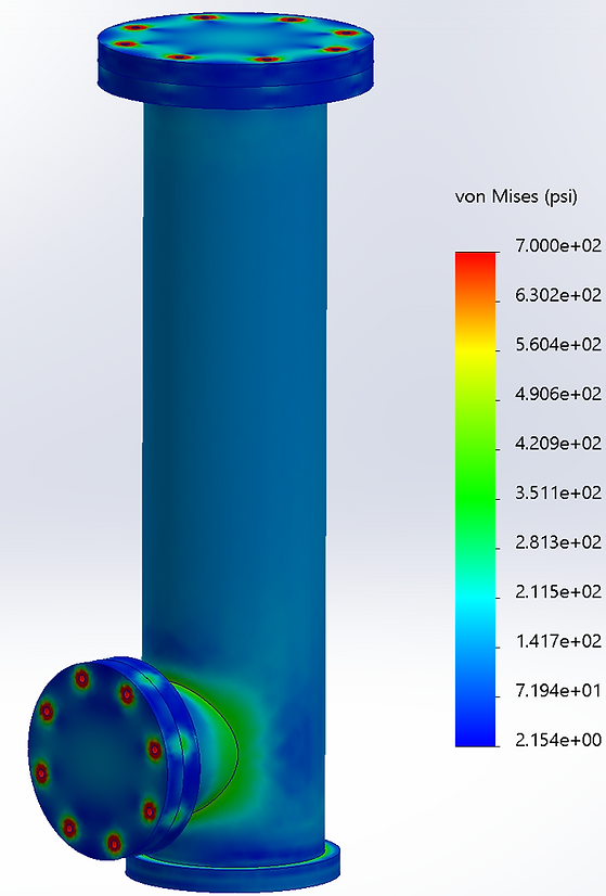
Finite Element Analysis
FEA was conducted to ensure structural integrity and sealing reliability under operational conditions. The analysis focused on two key areas:
Sealing Surface Deflection
-
Evaluated deformation at sealing interfaces to confirm that O-ring compression remained within optimal limits.
-
Guide design decisions on the required bolt patterns
Structural Stress Analysis
-
Assessed stress distribution to verify the chamber could withstand pressurization without excessive deformation or failure.
-
Identified critical stress points to refine the design and improve safety margins.
FEA and hand calculation results agreed, providing result validation.